Basic Introduction or Principle: We all are aware with the term "Generator". A device which converts mechanical energy into electrical energy is known as generator. This generator makes rotate with the help of some kind of external energy. When this energy extract from the energy of steam, the plant is known as steam power plant. A simple steam plant works on Rankine cycle. In the first step, water is feed into a boiler at a very high pressure by BFP (boiler feed pump). This high pressurized water is heated into a boiler which converts it into high pressurized super heated steam. This high energized steam passes through steam turbine (a mechanical device which converts flow energy of fluid into mechanical energy) and rotate it. Owing to extract full energy of steam, three stage turbines is used which is known as LPT (Low pressure turbine), IPT (intermediate pressure turbine) and HPT (High pressure turbine). The turbine shaft is connected to the...
AutoCAD is an initial program which is used in design any complex structure in both two dimensions and three dimensions. It is basic of all designing program. By using AutoCAD we can draw any design in a very short time period with great accuracy.
Learning AutoCAD, like learning any complex computer program, requires a significant commitment of time and attention and, to some extent, a tolerance for repetition. You must understand new concepts to operate the program and to appreciate its potential as a drafting and design tool. However, to become proficient at AutoCAD, you must also use the commands enough times to gain an intuitive sense of how they work and how parts of a drawing are constructed.
Starting the AutoCAD and introduction about its main screen:
Opening for the very first time can be an intimidating experience. Faced with such an expansive collection of tools, settings, and more, where do you start? To help you answer that question, this post breaks down the many components of the user interface into manageable segments and introduces you to basic operations such as opening drawings. To start AutoCAD first follow these instructions.
- Install the AutoCAD by using the default settings.
- Start AutoCAD by Start ->Programs -> Autodesk ->AutoCAD
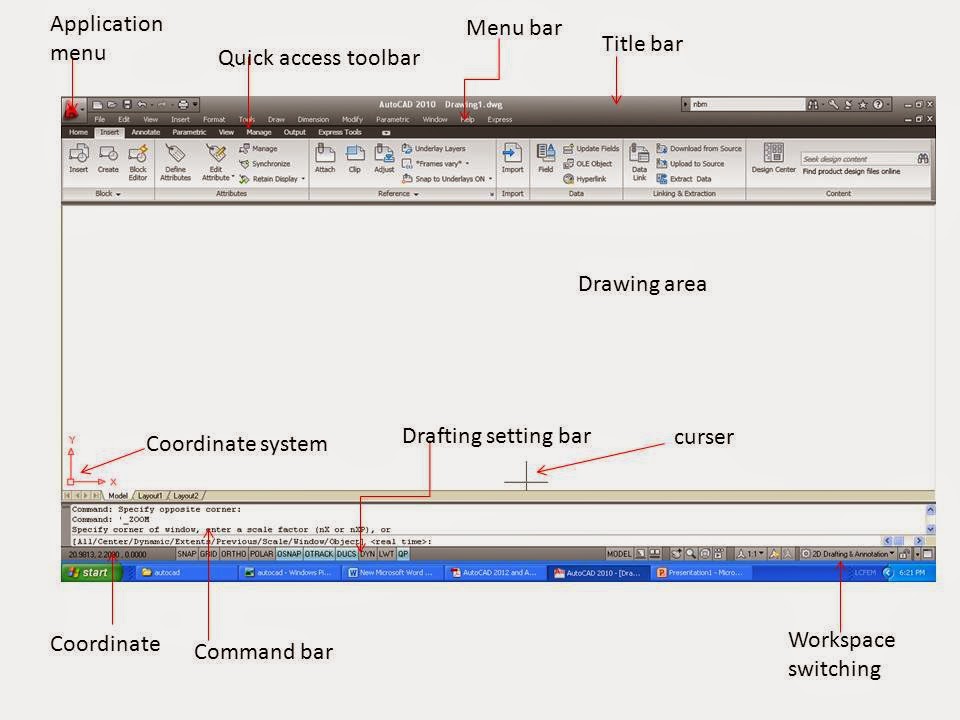
- After starting the AutoCAD opens to display its default user interface. This window will look similar to this figure.
- If it is not looking similar like this than go to workspace switching and change the mode to 2D drafting and annotation. You can also change it by ->menu bar -> tool ->workspaces ->2D drafting and annotation
- If menu bar is not displaying than check the left side of title bar. There is a drop down menu. Select show menu bar.

Here is the brief introduction of main screen.
Title bar:
The title bar is analogous to the title bar in any Windows program. It contains the program name (AutoCAD or AutoCAD LT) and the title of the current drawing with its path, provided a drawing other than the default Drawing.dwg is open.
The title bar is analogous to the title bar in any Windows program. It contains the program name (AutoCAD or AutoCAD LT) and the title of the current drawing with its path, provided a drawing other than the default Drawing.dwg is open.
Application menu:
Left side of the title bar you can find the application menu where you can find new (to open a new file), open (to open existing file), save, save as, print etc.
Left side of the title bar you can find the application menu where you can find new (to open a new file), open (to open existing file), save, save as, print etc.
Menu bar:
Below the title bar there is menu bar which is similar to any windows program with some additional menu like draw, dimension, modify etc.
Below the title bar there is menu bar which is similar to any windows program with some additional menu like draw, dimension, modify etc.
Quick access toolbar:
Below the title bar there is a ribbon which is known as quick access toolbar where you’ll find most of the AutoCAD commands and tools needed to complete any drawing task.
Below the title bar there is a ribbon which is known as quick access toolbar where you’ll find most of the AutoCAD commands and tools needed to complete any drawing task.
Drawing area:
Below the quick access toolbar, the blank middle section of the screen is known as drawing area where you draw the drawing.
Below the quick access toolbar, the blank middle section of the screen is known as drawing area where you draw the drawing.
Cursor:
The drawing area contains a cursor which can move all over the screen. In making a drawing in autocad cursor is very useful by which we draw the drawing.
The drawing area contains a cursor which can move all over the screen. In making a drawing in autocad cursor is very useful by which we draw the drawing.
Coordinate system:
This icon composed of two lines, labeled X and Y, in the lower-left corner of the drawing area is the UCS icon or coordinate system (UCS stands for user coordinate system). It indicates the positive direction for the x- and y-axes. It show the coordinate in which you are working.
This icon composed of two lines, labeled X and Y, in the lower-left corner of the drawing area is the UCS icon or coordinate system (UCS stands for user coordinate system). It indicates the positive direction for the x- and y-axes. It show the coordinate in which you are working.
Command bar:
Below the drawing area there is a command bar. Command bar (also called the Command window) is where you will tell the program what to do and where the program tells you what’s happening. It’s an important feature, and you’ll need to learn how it works in detail. By default, three lines of text are visible. When the Dynamic Input feature is active, much of the command window information is displayed alongside the cursor as well
Below the drawing area there is a command bar. Command bar (also called the Command window) is where you will tell the program what to do and where the program tells you what’s happening. It’s an important feature, and you’ll need to learn how it works in detail. By default, three lines of text are visible. When the Dynamic Input feature is active, much of the command window information is displayed alongside the cursor as well
Coordinate:
Lower left side of the command bar there is coordinate window, which show the coordinate of the cursor.
Lower left side of the command bar there is coordinate window, which show the coordinate of the cursor.
Drafting setting:
In the middle of the status bar there is drafting setting menu where you can select various drawing modes. It’s important to learn about the coordinate system and most of these drawing modes (Snap Mode, Grid Display, Ortho Mode, Object Snap) early as you learn to draw in AutoCAD. They will help you create neat and accurate drawings. It will discuss later is detail.
In the middle of the status bar there is drafting setting menu where you can select various drawing modes. It’s important to learn about the coordinate system and most of these drawing modes (Snap Mode, Grid Display, Ortho Mode, Object Snap) early as you learn to draw in AutoCAD. They will help you create neat and accurate drawings. It will discuss later is detail.
To conclude this quick introduction to the various parts of the Application window, you need to understand a couple of items that might be visible on your screen.
Change the cursor size background color of drawing area:
By default, AutoCAD uses a dark gray color for the drawing area. Some users prefer to customize this and several other user interface elements to a color palette of their own liking. As an example, some prefer the contrast ratio of a light background color such white. For change the cursor size and background color by follow the steps
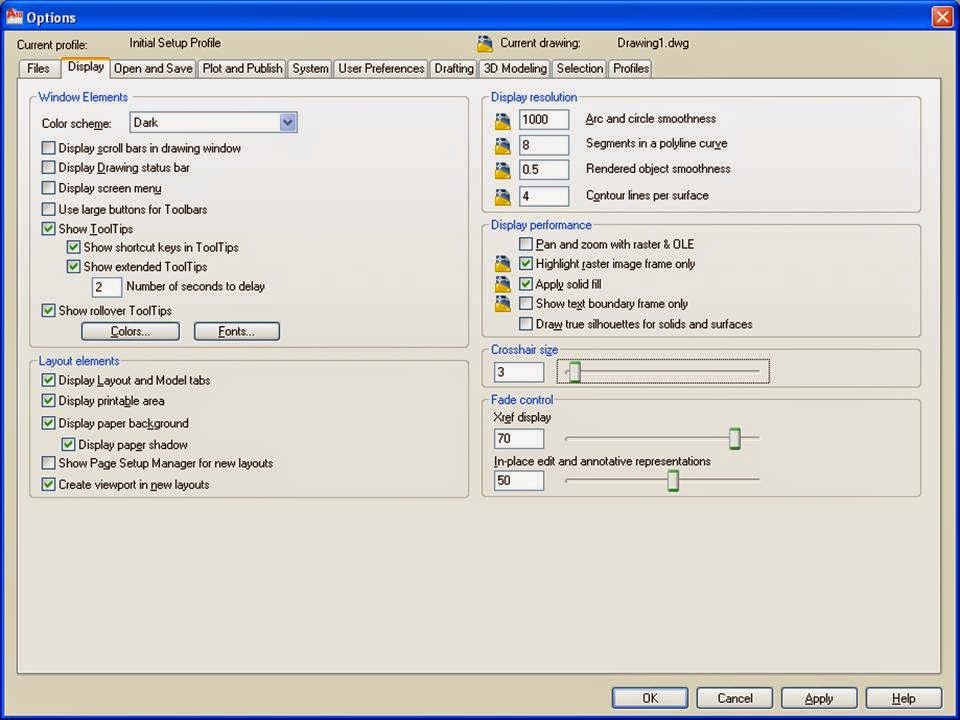
- Open the option dialog box by application menu->option or by right click on drawing area and choose option.
- Switch to the display tab.
- If you want to change the length of the lines of your crosshair cursor, go to the lower-right corner of the Display tab and move the slider to change the Crosshair Size.
- Choose the color within the window element group to change the background color.
- This opens the Drawing Window Colors dialog box, where you’ll customize the colors of the user interface to your liking.

Comments
Post a Comment