Basic Introduction or Principle: We all are aware with the term "Generator". A device which converts mechanical energy into electrical energy is known as generator. This generator makes rotate with the help of some kind of external energy. When this energy extract from the energy of steam, the plant is known as steam power plant. A simple steam plant works on Rankine cycle. In the first step, water is feed into a boiler at a very high pressure by BFP (boiler feed pump). This high pressurized water is heated into a boiler which converts it into high pressurized super heated steam. This high energized steam passes through steam turbine (a mechanical device which converts flow energy of fluid into mechanical energy) and rotate it. Owing to extract full energy of steam, three stage turbines is used which is known as LPT (Low pressure turbine), IPT (intermediate pressure turbine) and HPT (High pressure turbine). The turbine shaft is connected to the...
Today we will discuss about continuous variable transmission. We also discuss about advantages and disadvantages of CVT transmission. Till now we know that we use gear box to change the torque according to the driving requirement. For this we have four to five gear ratio which we shift and change the gear. But CVT is an automatic transmission that can select any desired drive ratio within its operating range. Unlike a conventional four or five-speed transmission, CVT is an infinite speed ratio transmission.
In the manual gearbox one problem facing that the one speed ratio is not fully efficient in the desire range. So the manufactures have to work on a new system which can obtain infinite speed ratio and there is one unique speed ratio for one speed. This is the basic idea of CVT.
Principle of CVT Transmission:
As an ordinary gear box CVT also works on the same gearing principle that when we attached a big driving gear to one small driven gear we obtain high torque and vice versa. But the CVT does not used gear to obtain speed ratio of transfer power. The other power transmission system belt drive used in CVT can change its diameters.
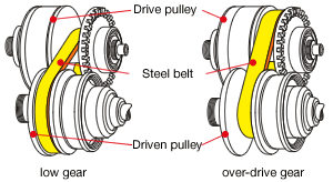
There are three main component of CVT which make is able to obtain infinite speed ratio transmission. These are a variable input driving pulley, a variable output driven pulley and a metallic belt.
Apart from these, there are also various microprocessors and sensors and even epicyclic gearing and clutch. Both the driving and driven pulleys are of variable diameter type. Each pulley is made of two 20 degree cones facing each other. A belt is there in the groove between the two cones. The belts are specially constructed to provide for the required flexibility.
The driving pulley is connected to the engine crankshaft while the driven pulley transfers motion to the drive shaft. When the two cones of the pulley are close together, the belt rides higher in the groove and the pulley diameter apparently increases, whereas the belt rides lower in the groove, making the effective diameter decrease, when the two cones of the pulley are far apart. These cones are moved closer or far apart using hydraulic pressure, centrifugal force or spring tension.
If diameter of driving pulley increases, the diameter of driven pulley decreases, and vice versa. This is done to keep the belt always tight. As the pulley change their diameter relative to each other, infinite number of gear ratio are obtained. For low gearing the diameter of small on the driving pulley and large on the driven pulley and for high gearing vice versa.
A conventional CVT uses the information from engine management ECU to determine the torque being delivered by the engine and accordingly the pressure exerted on the belt to avoid slipping. Further the drive is transmitted separately to forward gears and to reverse, through two multiple clutches. There are also two small hydraulic chambers for moving the variator pulleys instead of one larger chamber in case of conventional CVT, this reduces the power consumed.
Advantages and Disadvantages of CVT Transmission:
Advantages:
1. It provides the smoother ride compare to conventional gearing system.
2. It increases the fuel economy of vehicle by deliver optimum power range under all conditions.
3. It eliminates gear hunting while moving up and incline.
4. It decreases emissions due to better engine control under all conditions.
Disadvantages:
1. Torque handling capacity of a CVT is limited by the strength of the belt.
2. CVT has much shorter life compare to conventional gearing system.
3. CVT need large central distance which cannot be provided in inline configuration.
The CVT are already used by some manufactures like Nissan to obtain high efficiency. We can say that this technology continues growing and manufactures are looking forward with it. User loves them because of its efficiency and smooth riding. This system is also ecofriendly so the manufactures and government promoting it and soon it will adopted by most of manufactures. Audi’s Multitronic is also example of it.

Comments
Post a Comment